


Cooling Fan Technology by SANYO DENKI AMERICA
This site is part of SANYO DENKI’s official cooling engineering knowledge base.
Sanyo Denki has been developing fans for a wide range of applications and usages. There are many kinds of fans, but the main ones in the industry are as follows: single axial, counter-rotating, blower, and centrifugal fans. Each type of fan comes with a difference in PQ (static pressure-volumetric characteristic) curves and application usage. To understand these differences is to gain a large understanding of how these types of fans operate and how to read the fan’s PQ curves and specifications. This knowledge will help allow the user to build their system with the appropriate amount of power consumption, sound pressure levels, and appropriate fan selection without exceeding their thermal needs.
Fan air volume-static pressure characteristic diagram (P-Q curve) is a curve that shows the relationship between the air volume and the static pressure resulting from loss due to the pressure applied to the inlet and the outlet of the fan. Each fan design has a unique characteristic which is affected by the impeller design, type of motor, guide vanes, number of blades, and etc.
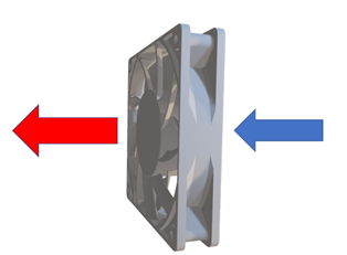
Fan with an inlet side and outlet side where airflow is discharged in parallel to the fans shaft where the impeller rotates.
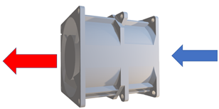
Two axial fans rotating in opposite directions to each other to create a discharge like a single axial fan but with a targeted tunnel airflow meant for higher static pressure performance.
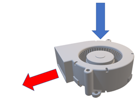
Inlet side of the blower is 90°C to the outlet side of the fan which offers spot cooling and applications that require a perpendicular intake and exhaust.
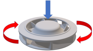
The rotating impeller of the fan drags the entering air into a circular motion and then is charged by the centrifugal force created by the rotation in a 360°C exhaust.
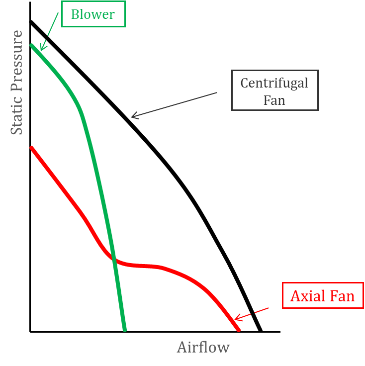
Each fan focuses on a unique application that requires airflow to be dispersed matching to the amount of static pressure needed. Each fan will have a different PQ curve that allows the end user to determine which fan best suits their application.
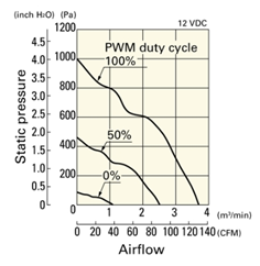
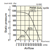
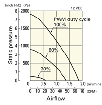
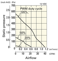
Each fan type comes with a variety of PQ curves which are shown in Figure 5.
Figure 5A will show the PQ curves overlapping for each fan.
Figure 5
Out of all the 4 types of fans, the single axial fan’s PQ curve has the most uneven regions. These regions right before the bend of the knee are what we call the stall region where the air has a mixture of turbulent and laminar airflow. The fan’s power consumption, current rating, and sound pressure levels will be abnormally high compared to the rest of the curve even at the highest static pressure peak in some cases.
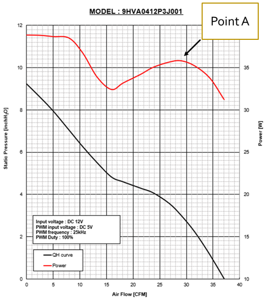
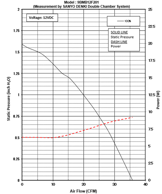
As an example, Figure 6 is a PQ curve of our 40x28mm 9HVA high-performance static pressure fan.
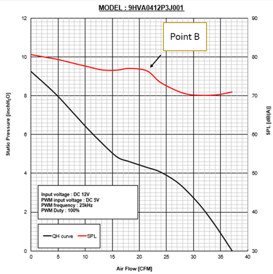
Figure 6A is PQ vs Power. Figure 6B is PQ vs SPL (Sound Pressure Level).
The 2 PQ curves have the same exact operating conditions but as you can see, right before the bend of the knee the power consumption and sound pressure levels are higher (Point A in figure 6A and Point B in figure 6B). If the customer’s operating point is within this stall region, the fan will generate a lot more power and sound causing issues with the end user who might be sitting next to the machinery, or the amount of power consumption from the PSU (power supply unit). System impedance is the resistance to air within a device which can be measured using the proper test equipment. The operating point is where the airflow vs static pressure characteristics intersects the system impedance curve.
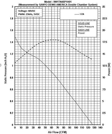
Counter Rotating fans were designed for high static pressure and linear airflow for applications that have high back pressure. For instance, servers, storage systems, communications equipment, and power supplies. These fans normally generate a lot of power due to 2 fans working in tandem but rotating in opposite directions. Figure 7 will show the inlet, outlet, and total power consumption at 100% PWM duty.
Counter Rotating PQ’s curve still has the bend of the knee, but the focus is the high static pressure in the majority of the region throughout the curve.
By knowing the power requirement of the customer’s system, we’re able to rule out counter-rotating fans that exceed that requirement.
The counter rotating fan’s PQ vs SPL curve differs from the single Axial fan.
Figure 8 will show how after the bend of the knee the SPL dramatically drops and then picks back up again as the airflow becomes more laminar.
This is due in part to the inlet fan handling the majority of the airflow and will normally have a higher RPM. This is a SANYO DENKI counter rotating design concept as the output has a better total PQ curve that stabilizes the static pressure. When static pressure becomes higher, the airflow becomes more turbulent causing more wind noise.
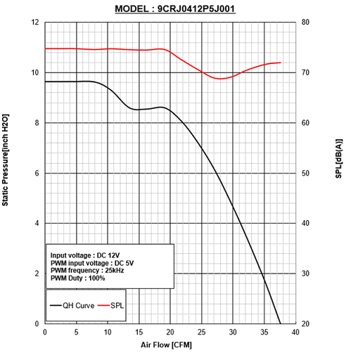
Centrifugal fans are based around a rotating impeller which pulls in the entering air and then expels the air in a circular motion. Particularly for the larger centrifugal fans, they tend to be ideal for telecom brackets and industrial applications. Both fans don’t have a stall region due to unique blade and structure design, which allows users to have a wider range of operating points against the system impedance curve compared to axial fans. Blowers work off the same theory as any other centrifugal fan but there is a difference with the intake and outtake design for a more spot cooling application. Figures 9A and 9B will show the PQ vs Power curves for a blower and centrifugal fan. The power consumption and noise factor can be lower than an axial fan at the same operating point.
The PQ curves of each fan type vary, and each fan type comes with fan series. SANYO DENKI has a large lineup of splash proof, low power consumption, silent, long life, and high static pressure fans. Each of those fan series will come with a difference in power consumption, sound, efficiency, and usage. By being able to understand the system impedance curve of the system, the end user can align that curve against SANYO DENKI’s PQ curves of a selected fan and make a good selection that is appropriate to their system.
Written by Morris Sith Saypanya
This article is part of SANYO DENKI AMERICA’s San Ace cooling engineering knowledge base, sharing practical guidance engineers use when working with DC fans in electronic cooling designs.
SANYO DENKI has been a trusted provider of cooling solutions for various industries, with fans being a crucial component in many advanced devices. Contact us for a quote, or to discuss your device's customization requirements.
Our experienced application engineers and field engineers will provide support on the customization or any other technical support for your equipment. Contact our representatives or distributors to start discussing your next project.
Contact Us