

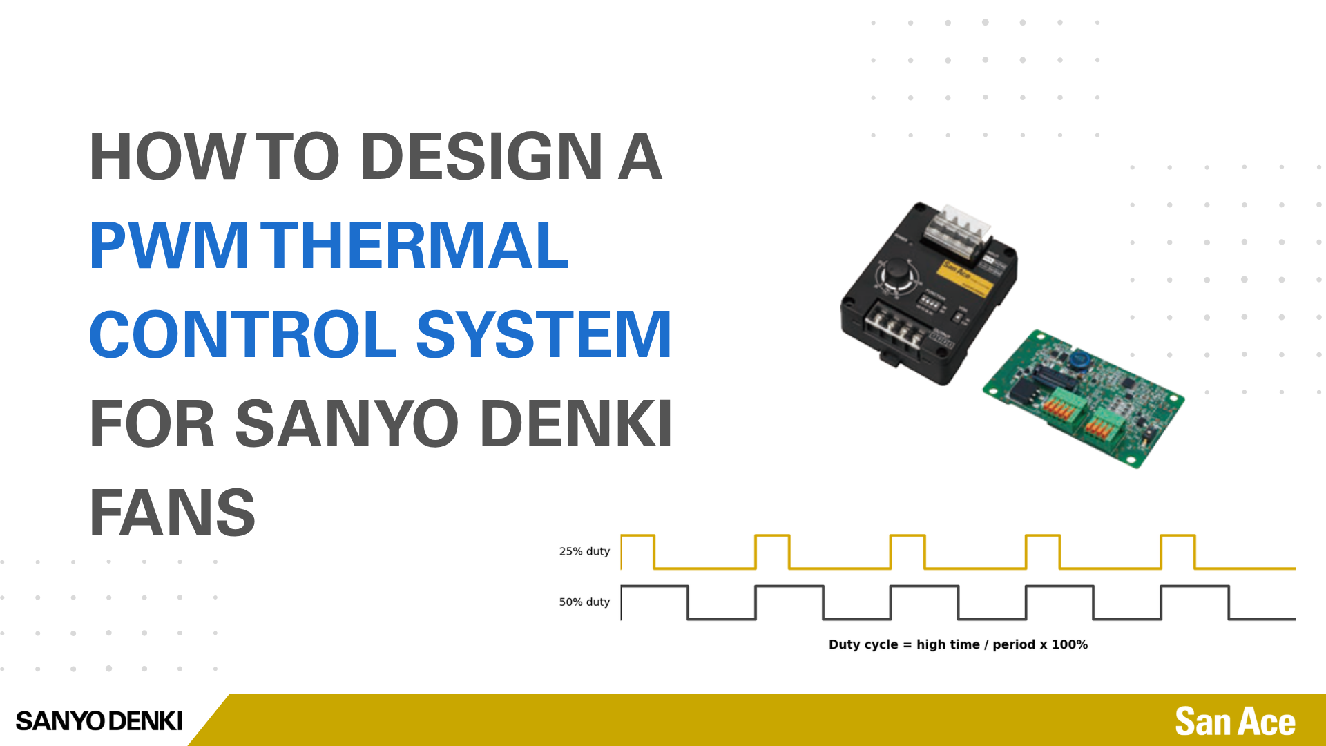
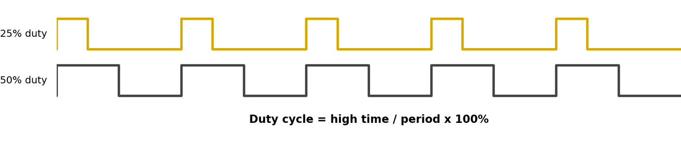
Modulation of fan speed is a necessity in high efficiency system operations in today’s power-hungry electronics world. For SANYO DENKI fans, Pulse-width modulation (PWM) is the preferred way to command the speed of a compatible four-wire DC cooling fan while keeping the fan motor supplied with constant DC voltage. By varying the percentage of high signal on a standard frequency signal, called the duty cycle, the fan’s internal electronics translate that command into rotational speed. This is covered in more detail as part of our previous PWM control blog.
Why Engineers Use PWM Speed Control
PWM helps a cooling system match airflow to the actual thermal load. During light-load operation, reducing fan speed can lower acoustic noise and input power while preserving the ability to increase fan speed during peak thermal usage. A great example of this is in systems where external weather factors may impact the thermal load of a system. During colder months or time of day, a system may not require the same fan cooling performance as hotter periods.
The PWM signal can be generated by a microcontroller, FPGA, system-management controller, or a dedicated PWM controller. Let’s discuss these options and when each may be of use.
Designing a Fan Control System
When designing system control for fans, it is important to understand what control properties you need for your overall system design. A fan control system may include four main parts: sensors, control logic, method of interface, and the fan. To use a simple example, this brake down into the following categories:
The Brains– How you make decisions on what speed the fan should be
– FPGAs
– Microcontroller Unit (MCU)
The Senses– How you determine if your system is operating properly
– Thermistors
– Pulse Sensors
– Pressure Sensors
The Muscles– How much thermal performance are you generating
– Fans
– Liquid pumps
The Neurons– How you plan to control your thermal devices
– PWM control
– Variable voltage control
Different control methods will handle these functions differently with varying degrees of control.
PWM Signal Interface
There is a verity of methods which can be utilized to implement PWM into your thermal system. For SANYO DENKI fans, this commonly can be defined into two primary methods: TTL and Open drain/collector.
1. TTL PWM Control (Recommended)
TTL control uses a digital signal that switches between a high voltage and a low voltage. With a direct connection, the PWM output from the system controller connects to the fan’s PWM input, and both devices share the same signal ground.
The controller’s high and low voltages, output current, maximum voltage, and PWM frequency must meet the fan’s specifications. Many SANYO DENKI PWM fans use a 25 kHz, 3.3 or 5V signal, but the requirements can vary by fan model.
Do not assume that a 3.3V output from an FPGA or MCU will work with every fan. First, confirm that the 3.3 V signal is high enough for the fan to recognize it as a logic-high voltage signal.
Common sources of TTL PWM signals include FPGA and MCU PWM outputs. The SANYO DENKI PWM Controller is another device that can generate PWM signals for fan speed control.
2. Open-Drain and Open-Collector PWM Control
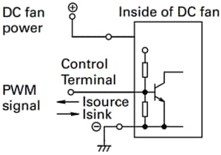
Open-drain and open collector PWM control are comprised of discrete components that will generate a signal. These circuits can use transistors, resistors, capacitors, and timing devices to generate a PWM signal and pull the fan’s control line low. An open-drain or open-collector circuit can pull the fan’s PWM control line low, but it cannot actively drive the line high. A pull-up circuit inside the fan, or an approved external pull-up resistor, brings the signal back to the high state. Many SANYO DENKI standard fans include an internal pull-up resistor.
This circuit can help connect devices that use different logic voltages and can protect low-voltage controller outputs. SANYO DENKI fans can support open-drain or open-collector PWM signals when specified. However, this type of connection may change how the fan speed responds to the PWM duty cycle, so the requirements for the specific fan model should always be checked.
3. SANYO DENKI PWM Controller
The PWM controller is designed to be your central nervous system for thermal control. It doesn’t have the processing or decision-making capability to intelligently control a fan; however, it offers a wide verity of features for management of different control inputs and ease of use with fans.
This makes it optimal for prototypes, test benches, retrofits, and equipment that does not already generate a qualified PWM signal. We recommend the SANYO DENKI Box-type PWM Controller as your starting point in any design process as it eliminates the need to design a pulse-generation circuit and provides a plug-and-play PWM function generation for usage with a fan.
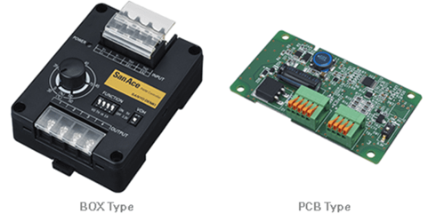
For flexibility of use, the PWM control offers 4 different methods of input for control: internal variable resistor, external variable resistor, voltage control, or thermistor control. This gives flexibility during early design stages to experiment and test PWM control of the fans as part of a lager design package without fully tooling up board components or programing software to control fan during thermal testing and design.
While it doesn’t do its own processing, it can be integrated with a variety of programable options to function as a closed loop control system. In addition to the Box-type controller, we also offer board style PWM controllers which can be better suited for mass production implementation.
For more details on how to use these functions on the SANYO DENKI PWM controller, see our blog here.
Choosing Control Architecture
Practical FPGA/MCU Implementation Within Your System
FPGA and MCU applications can provide the processing and decision-making capability within a PWM thermal control system. These devices can be integrated into many board applications as a dedicated control for your thermal fans in a system. With processing capability, they can be programed to intelligently monitor and modulate fan speed so that they are optimally used in your system.
Many FPGA’s or MCU will come built with PWM function generation capability and can be programed to match the specific frequency and voltage requirements to interface with a fan. Additionally, proper implementation can interpret a wide variety of sensor inputs to process and control fans according to system demand. This can also be utilized for monitoring fan health by measuring pulse sensor signal output from individual fans. If a fan fails or fully stops rotation, closed loop feedback can alter the performance of other fans to compensate for the failure or send technician requests for repair.
This functionality is excellent for use in a thermal system since optimal operation of a fan can fluctuate depending on the specific operation conditions that can change throughout its potential usage. The ability to program a system to interpret and adapt to these conditions will keep your thermal system operating at peak efficiency. While operating a fan with the use of an FPGA or MCU may be one of the optimal usages of a fan system, it requires tooling and significant engineering resources to implement into a production scale system. While it will be better long term for a system implementation, the downside is up-front design time and cost.
PWM Thermal Control using Analog IC's
Analog ICs can be used to generate PWM signals for fan speed control without requiring firmware development.
These circuits provide a simple solution for applications that require only basic fan speed control. Depending on the circuit implementation, external components such as resistors, potentiometers, thermistors, and capacitors can be used to configure the operating characteristics of the PWM generation circuit.
Unlike FPGA- or MCU-based solutions, circuits built around analog ICs typically do not provide features such as fault monitoring, communication interfaces, data logging, or advanced adaptive control algorithms. This approach can be particularly useful for prototyping, performance evaluation, or applications where development cost, software complexity, and implementation time must be minimized.
As with any PWM control method, the output voltage levels, drive capability, PWM frequency, and signal interface requirements should be verified to ensure compatibility with the specifications of the fan being used.
Please note that these circuits are purely as reference and may need alteration depending on the specific fan and performance capabilities for their intended use.
PWM Control Methods Comparison
| Control Method | Design Cost | Flexibility | Monitoring | Best For |
|---|---|---|---|---|
|
Box-Type PWM Control |
Low |
Medium |
Limited |
Production Systems |
|
MCU |
Medium |
High |
Excellent |
Production Systems |
|
FPGA |
High |
Very High |
Excellent |
High-Speed Applications |
|
Open-Drain Circuit |
Low |
Low |
None |
Simple Designs |
Recommended Design Proces
Start by selecting a PWM-capable San Ace fan and checking its PWM signal requirements and duty-cycle speed curve. Connect the fan to a rated DC power supply and make sure the wiring, connectors, and protection devices can handle the maximum current. Then choose how to generate the PWM signal.
– Choose the control method: The SANYO DENKI PWM Controller is a simple option for manual, voltage, variable-resistor, or thermistor control. A MCU, PLC, or FPGA is better when the system requires independent control of several fans or more advanced control functions.
– Confirm signal compatibility: Before selecting a TTL, open-drain, or open-collector connection, confirm the fan’s voltage, current, and frequency requirements.
– Plan for fault conditions: For critical applications, define a safe response to high temperatures or control-signal failure. Use the tachometer signal to confirm that the fan is operating.
– Test under operating conditions: Validate the system under its expected temperature, voltage, airflow, cable-length, and electrical-noise conditions.
As a safety measure, SANYO DENKI standard fans will default to 100% PWM duty when a PWM signal is not detected. This prevents any loss of signal failures from diminishing cooling performance within your system and potentially causing critical components to overheat.
Common Integration Errors
Do not assume that the PWM duty cycle directly equals the same percentage of rated fan speed. For example, a 50% duty cycle may not produce exactly 50% of the rated RPM. This also relates to stopping the fan, see more info about zero stop functionality in fans. The PWM signal should be applied to the fan’s dedicated control lead rather than pulsing the fan’s power or ground connection. Before connecting a 3.3 V or 5 V controller output, confirm that the voltage is compatible with both the fan and the controller by contacting your local SANYO DENKI representative for a full specification drawing. Open-drain and open-collector circuits may also invert the PWM signal, so the control direction must be verified. When one output controls several fans, check the total current and signal quality. In critical equipment, use the tachometer signal to confirm that the fan is rotating.
Conclusion
PWM fan control can be a game changer for reducing noise, improving energy efficiency, and managing cooling performance in electronic devices. It can also provide peace of mind in critical applications by supporting system monitoring and fan performance feedback. When your system design necessitates PWM control, make sure the control method operates within the voltage, frequency, current, and duty-cycle requirements. In prototyping and rapid development needs, consider the SANYO DENKI PWM Controller for an integration ready option for testing and controlling fan performance. For any thermal management or fan needs, please contact our SANYO DENKI team for recommendations on integrating PWM functionality into your system.
Written by Ryan Murphy
This article is part of SANYO DENKI AMERICA’s San Ace cooling engineering knowledge base, sharing practical guidance engineers use when working with DC fans in electronic cooling designs.

About SANYO DENKI
SANYO DENKI has been a trusted provider of cooling solutions for various industries, with fans being a crucial component in many advanced devices. Contact us for a quote, or to discuss your device's customization requirements.
Our experienced application engineers and field engineers will provide support on the customization or any other technical support for your equipment. Contact our representatives or distributors to start discussing your next project.
Contact Us