a tutorial on PWM Speed Control in Brushless DC Cooling Fans

With faster and more powerful ICs being designed into smaller, more densely packed form factors, the heat these ICs generate becomes a serious issue that can no longer be resolved with passive cooling solutions alone. For many applications, the next level in thermal management involves active cooling with the use of high-performance, brushless DC cooling fans.

Engineers select a fan based on “worst-case scenarios.” In other words, when the system is running at peak usage and a fan(s) fails, the system must be designed to compensate for the loss of a fan(s). To do this, engineers must design in a higher-performing fan than is required.

Once a fan with the required airflow has been identified, engineers must also consider the noise generated by the fan, the power the fan consumes, and the life of the fan. Since all of these variables are a function of the fan speed, the ability to control the fan speed using PWM speed control allows the system to balance these variables based on the thermal load at any given moment.

1. The Basics: What is PWM Speed Control?

A PWM signal is generated by the host system and sent to the fan’s internal IC via a lead wire attached to the fan. This signal consists of a repeating pattern of square wave pulses. The pulses are square because the signal is either instantaneously high (on) or instantaneously low (off). See Figure 1.

a graph showing PWM signal by SANYO DENKI Cooling Fan

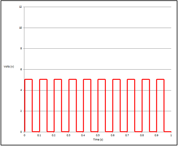
Figure 1- A PWM signal consisting with a 10 square wave pulses per second

The PWM signal is defined by two parameters: the frequency (f) and the duty cycle (%).

The frequency (f) is constant and is measured in hertz (Hz). It refers to the number of pulses per second. Figure 1 has a frequency of 10 Hz.

The duty cycle is calculated as the percentage of time that a single pulse is in a high state (on) relative to the length of time the pulse lasts. See Figure 2.

a graph of PWM duty cycle by SANYO DENKI Cooling Fan

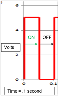
Figure 2 – A single pulse lasting 0.1 seconds, in a high state for 0.05 seconds. 

The duty cycle is calculated as: (.05 )/(.1 ) = 50% 

The underlying principle of PWM is that the fan speed will vary linearly with the duty cycle. By varying the duty cycle of the signal (modulating the width of the pulse), the fan speed can be varied. SANYO DENKI fans are designed for use with a standard 25kHz PWM signal frequency.

Let’s look at how using PWM to vary the fan speed affects the airflow, power consumption, and noise of the fan.

2. Advantages of Using Fan Speed Control

While a fan is rotating at full speed to remove the heat generated by a system at full capacity, the fan is also producing the maximum amount of noise and consuming the maximum amount of power. When a system is running at nominal, the fan can be throttled back to lessen the airflow, noise generated and power consumed.

Dimensional analysis can be used to illustrate the dramatic effect lowering a fan speed (N) can have on the flow rate (Q), noise (S), and power (W).

2.1 Airflow (Q)

As mentioned previously, the airflow increases linearly with the fan speed. If the fan speed is decreased by 25%, the airflow decreases by 25%. This linear relationship can be seen in Figure 3.

a graph of airflow vs speed RPM by SANYO DENKI Cooling Fan
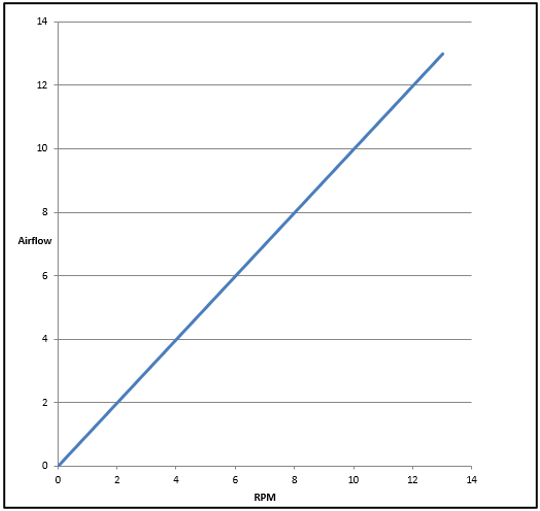
Figure 3 – illustrates the relationship between fan speed and airflow (Q). 

The relationship is given by the equation: Q = N

2.2 Noise (dB's)

Figure 4 illustrates the logarithmic relationship between the fan speed and the sound pressure the fan generates. Again, the noise generated by a fan is also not linear. If we decrease the fan speed by 25%, we know the airflow will drop by 25% and the power will drop by 60%, and now we know the noise will drop by approximately 6 dB. The general rule of thumb is, for every 3 dB the sound pressure drops, a fan will subjectively sound about half as loud.

a graph of Sound dB vs speed RPM by SANYO DENKI Cooling Fan

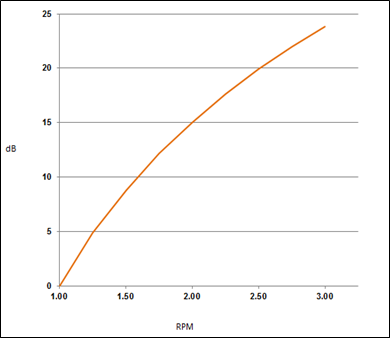
Figure 4 illustrates the relationship between the fan speed, sound pressure, or noise the fan generates. The relationship is given by the equation:

Δ dB = 10 log(N2/N1)5

2.3 Power (W)

The power a fan consumes vs the speed the fan rotates is not a linear relationship. Figure 4 illustrates the parabolic relationship between the fan speed and the power the fan consumes. To reiterate, while a linear fan speed drop will correlate to a linear airflow drop (e.g., 25% lower Q and N), the power would drop by 60%.

a graph of power watts vs speed RPM by SANYO DENKI Cooling Fan

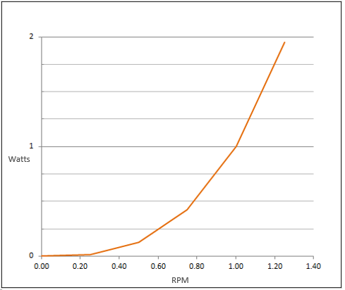
Figure 4 – illustrates the relationship between fan speed and power consumed by the fan. 

The relationship is given by the equation: W = N^3                 

3. Summary: PWM Control is the Tool to Balance Variables

As today’s systems continue to get more powerful, smaller, and denser, the demand for higher airflow fans increases. When designing in the right fan, design engineers must balance the airflow requirements within their system with the power requirements to run the fans and the noise constraints of their particular application. PWM is a tool that allows engineers to balance these variables based on the demands put on their system at any given time.

Written by Daren Perez

To read more articles by our engineers, click here.

About SANYO DENKI

SANYO DENKI has been a trusted provider of cooling solutions for various industries, with fans being a crucial component in many advanced devices. Contact us for a quote, or to discuss your device's customization requirements.

Our experienced application engineers and field engineers will provide support on the customization or any other technical support for your equipment. Contact our representatives or distributors to start discussing your next project.

Contact Us

Leave a Reply

Your email address will not be published. Required fields are marked *