Brief Overview of DC Fan Sensors

sanyo denki SanAce40 HVA modelIn the DC fan world, fans come in two, three, and four wire configurations as follows:

Two wire – Just power and ground, fans run at full speed, no speed control or pulse sensor (AKA Tach) output.

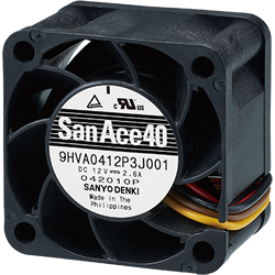
Three wire – Power, ground and pulse sensor output to monitor RPMs. No speed control.

Four wire – Power, ground, pulse sensor output and PWM input control for varying speed.
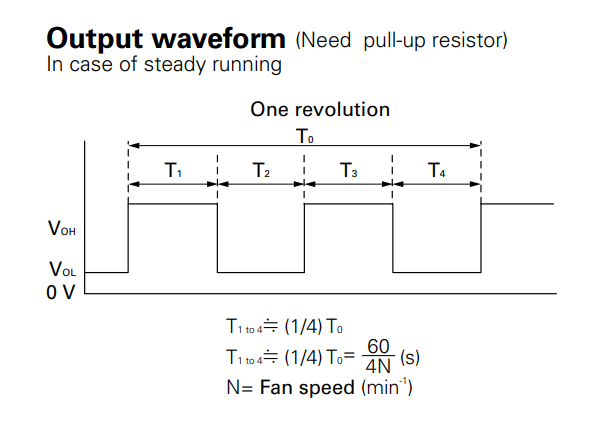
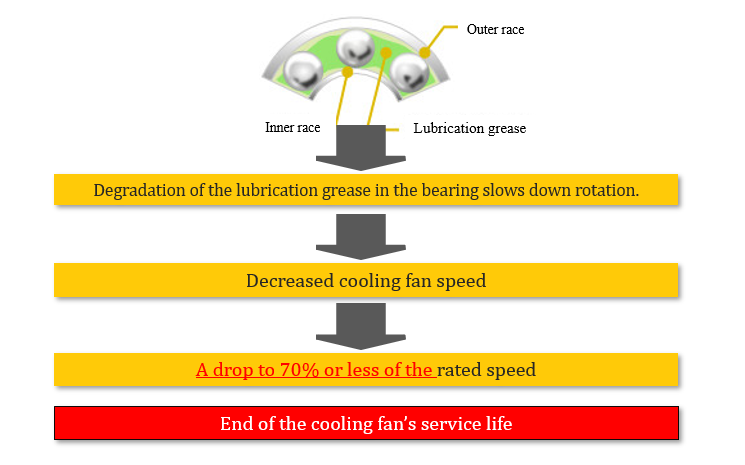
Role of The Tach Sensor from Lock Rotor to Monitor Speed

Originally, the third wire was added to provide what is called a “lock rotor” feature, which provides a logic high level if the impellor stopped rotating to alert your system to shut down and prevent overheating. However, years later when fans were introduced with speed control (via PWM lead wire), the third lead wire was offered as a pulse sensor output so the RPMs could be monitored when the PWM duty cycle was changed.  

output waveform of fan sensor

Note two pulses per revolution for the pulse sensor output is the most common industry practice. 

This would also still provide an alert like the “lock rotor” feature since if the impellor stopped rotating, the output pulses would stop at either a logic high or logic low.  Note while the lock rotor feature is still available today, the pulse sensor output has become much more popular and common. 

Service Life Monitoring Benefit of Pulse Sensor

A benefit overlooked of the pulse sensor output is that it can indicate the health or the service life of the fan so you can plan for maintenance.  Let me explain, we at Sanyo Denki view a fan coming to an end of its service life when its RPMs drop to 70% of the nominal value. 

service life of cooling fans

For example, a fan which has a nominal RPM spec of 10,000 at full speed, shows the speed declining as time goes on over years of continuous use. Once it approaches 7,000 RPMs, the customer’s monitoring firmware can send a flag signal to indicate that the fan will need to be replaced.  This comes in very handy when other planned system maintenance is needed such as in remote locations where doing maintenance is not available year-round based on accessibility or having your system shut down without warning.

Note that this feature works for both open loop fans (which don’t have feedback) and for closed loop fans.

Let me explain for closed loop fans (fans that have feedback so the speed remains constant when the load changes) the fan’s current draw will slowly increase to account for the additional load from the grease degrading but when it reaches the internal current limit, the rotation speed will start to decrease so this can still be used to monitor for the heath/service life of the fan.

When Pulse Sensor is Unrequired

So why would you not want a pulse sensor output?

  • Low tech, noncritical application, not concerned with monitoring if the impellor has stopped rotating (has other built in OTP (Over Temp Protection) circuit in their system.
  • Used in a low cost, disposal, short lived application.
  • Misconception that the pulse sensor feature will add too much to the fan cost (but only adds pennies per fan).
  • Customer doesn’t want to create circuitry to monitor the RPMs.


In closing, the benefit of using a three-wire fan with pulse sensor output is to monitor the health of the fan to determine when the fan service life is approaching replacement and to schedule maintenance.

Written by Gary Masessa

SANYO DENKI AMERICA
TECHNICAL CENTER
Cooling Sales Territory Map
3 thoughts on “An Overlooked But Useful Benefit Of The Pulse Sensor On A DC Fan”

Leave a Reply to WHAT IS THE ZERO STOP FEATURE IN A DC FAN? - Cooling Fan Technology by SANYO DENKI AMERICA Cancel reply

Your email address will not be published. Required fields are marked *