To start with, fans do not create airflow. A fan simply imparts energy to the air particles which accelerate the air forward. To understand this counter intuitive concept, let’s start with some basic fan dynamics. A fan converts electrical energy, (electricity), into mechanical energy, (rotating impeller). When the rotating impeller blades come into contact with air particles, the impeller imparts energy to the air particles. This energy takes two forms.
- Kinetic energy,
- Referred to as KE moving forward
- It is the velocity component of the air molecules
- KE =

- Potential energy,
- Referred to as PE moving forward
- PE is the pressure =

- PE is energy stored in the deformation of the air molecule.
To get a more intuitive understanding of how the mechanical energy from the rotating impeller is imparted to the air molecules, let’s look at a golf analogy.
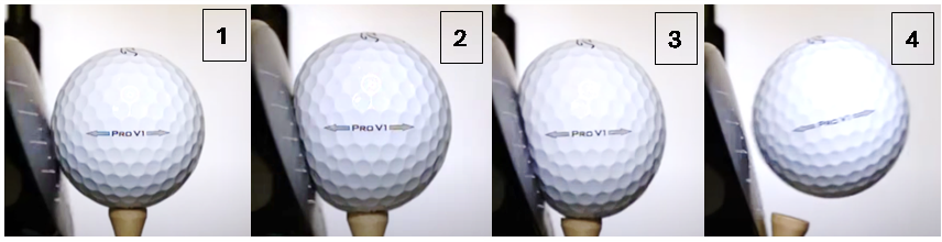
A rotating golf club imparts energy to a golf ball in the same way a rotating impeller imparts energy to an air molecule. The below three picture frames help illustrate this point.
Frame 1 – The moment right before the rotating golf club impacts the golf ball; no energy has yet been transferred to the golf ball. Therefore, there is no rotation, no plastic deformation, and no acceleration of the golf ball.
Frame 2 – Contact is made, the golf ball immediately begins to compress as the swinging golf club imparts energy to the ball. This energy is at first stored as PE in the elastic deformation of the ball.
Frame 3 – The ball continues to deform as more energy, imparted by the golf glub, is stored as PE. The ball also begins to accelerate forward as KE is imparted to the ball also.
Frame 4 – The PE stored as elastic deformation of the golf ball is converted to KE as the ball “snaps back” to its original shape, contributing to the balls forward motion. Since all the energy imparted to the ball by the rotating golf club is now in the form of KE, the ball is at its maximum speed.
One item this analogy is not able to illustrate; the distribution of KE to PE imparted by the golf club will not change each time the ball is hit assuming the velocity of the swing does not change. We will re-visit the distribution of energy topic later in this paper.
So far, we have discussed how a stand-alone fan creates airflow. To understand how to select a suitable fan for a particular application we must understand how the air actually flows in both free air and impeded air.
The importance of the energy carried by an air particle will become more important when we discuss the dynamics of airflow. For now, let’s take a closer look at how fans create airflow.
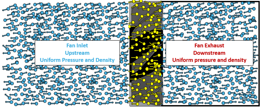
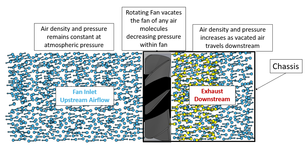
As the fan begins to rotate, the impeller comes into contact with the yellow air molecules in the path of the impellers rotation. This accelerates the air particles downstream, as illustrated below. This is a burst of air, not airflow.
The movement of the yellow particles downstream has upset the equilibrium. The air density downstream, and therefore the air pressure, is no longer uniform. A pressure gradient has formed between the atmospheric air pressure upstream and the lower pressure (vacuum) within the fan, see below figure 1.
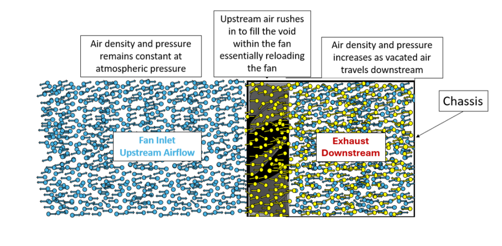
The pressure gradient effectively forces the upstream air to “reload” the fan, see
figure 2 below. Without this pressure gradient forcing air into the fan each time the fan impeller expels the air within the fan, we would not have airflow. This is how the pressure gradient, not the fan, creates continuous airflow.
The pressure gradient effectively forces the upstream air to “reload” the fan, see figure 3. below. Without this pressure gradient forcing air into the fan each time the fan impeller expels the air within the fan, we would not have airflow. This is how the pressure gradient, not the fan, creates continuous airflow.
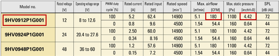
In the real world, fans are designed into confined spaces with components that interact with, and resist, the flow of air. As the rotating impeller continues to accelerate air particles downstream the air accumulates due to a slowdown in the airflow velocity. The decrease in velocity is a function of the system’s impedance. The system impedance is a measure of the resistance to airflow within the system and is based on the density of the system architecture itself. Density refers to the ratio of components to free space in the system. The more impedance a system has the lower the CFM the fan can produce. The 9HV0912P1G001 fan has the ability to produce 180 cfm in free air, however, would produce less than 180 cfm through a system with impedance.
As mentioned earlier, impedance is a characteristic of a system’s architecture. The level of impedance within a system determines the amount
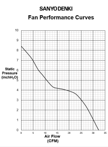
of airflow a given fan can move through it, indicating that airflow is a function of this system characteristic. Based on this relationship between airflow and system impedance, the performance of a fan is commonly characterized by its Pressure-Flow (P-Q) curve. This curve graphs the static pressure the fan is capable of developing across a range of airflow rates.
Each point on the curve references the airflow resulting from the impedance a system has. This point is known as the operating point within the system. Different fans produce different amounts of back pressure therefore a PQ curve is specific to a specific fan in a specific system. A fan which can produce more/less pressure will be able to produce more/less airflow in the same system and will have a different PQ curve. Essentially the PQ curve tells us how much airflow a fan can continuously produce given the back pressure created by a system impeded.