

Cooling Fan Technology by SANYO DENKI AMERICA
Providing Cooling Solution with High Performance and Reliability
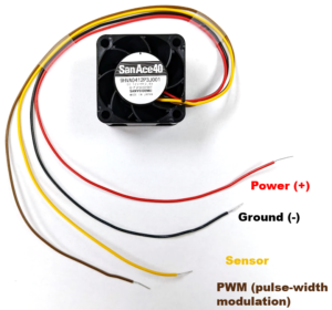
The adoption of cooling fans for thermal management also brings up the question of how-to setup and monitor fans for applications such as 1U server racks, information and computer technology (ICT) equipment, high-performance computing (HPC), medical devices, air filtration, semiconductor processing equipment, etc. An example San Ace product, 9HVA 40x28mm (9HVA0412P3J001), has a 4-wire configuration and the associated wiring functionality of power, ground, sensor, and PWM is shown in Figure 1.
This blog post will focus on sensors for monitoring fan performance status. While the power (+) and ground (-) connections are the two wires necessary for the fan to operate, supplying the power alone would not necessarily provide adequate feedback to the design engineer or operator on whether the fan is operating, or if it is operating at full capacity, or operating at low-speed, or if the rotor is locked.
There are various types of sensors that Sanyo Denki integrates into San Ace products, including lock sensors, low-speed sensors, and tachometer (tach or pulse) sensors. Sanyo Denki can customize fan models such as 9HVA0412P3J001 with a suitable speed sensor required for the specific application. The cooling fan sensor output and how it is integrated into a system is dependent on use case, the logic on the control board, and what information is necessary as feedback for a system. While lock and low-speed sensor outputs provide high and low signals that signify if the fan is operational or not, the tach sensor provides a more data-rich signal which can be interpreted to measure the exact revolutions per minute (RPM) of the fan.
A common type of sensor output is the high and low signal. Two examples include the lock sensor and low-speed sensor, where the switch of the signal from low to high is triggered by a change in operation of the fan rotor.
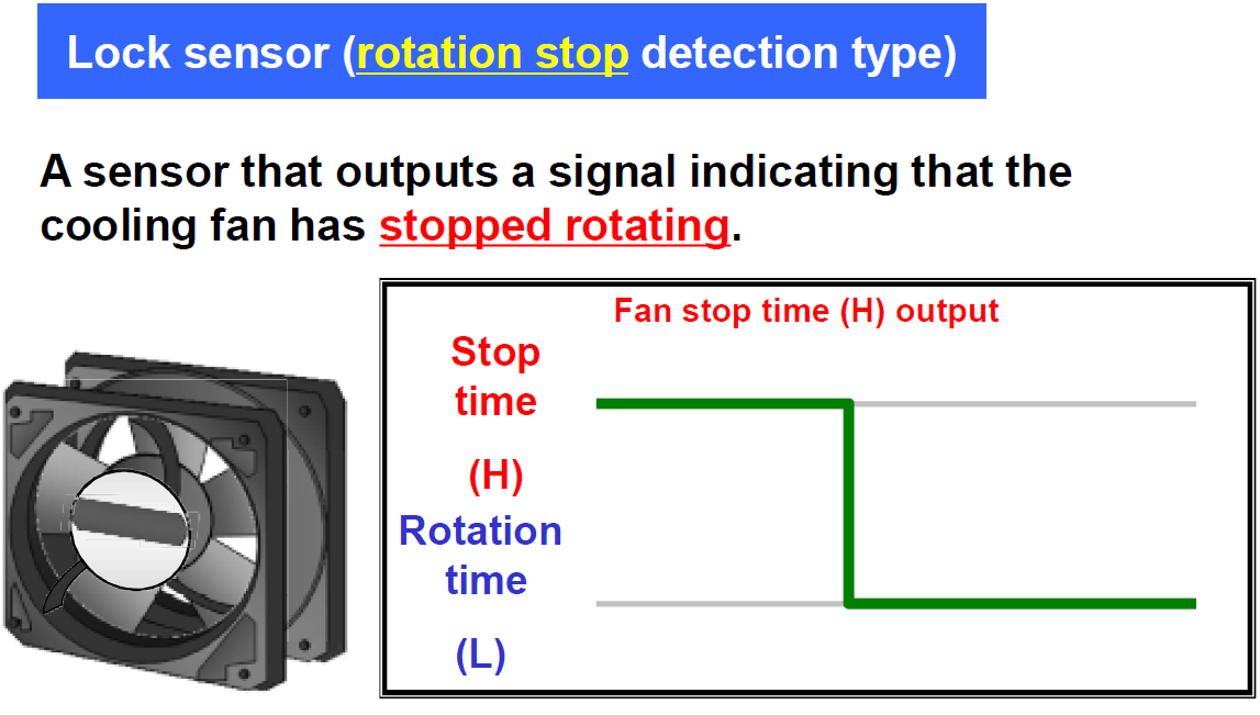
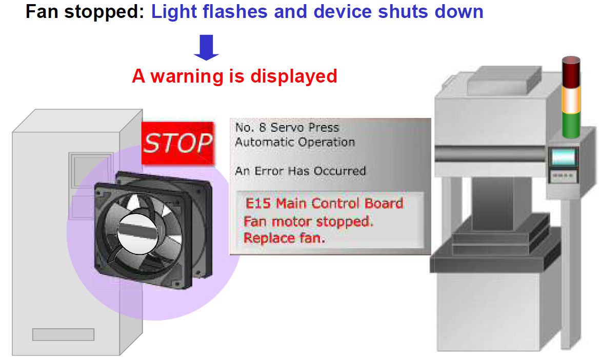
In the case of a lock sensor, there are two states of the sensor output. When the fan is operating normally (i.e., the rotor is running), the signal is low. If the fan fails or becomes non-operational, the lock sensor will detect a locked rotor and output a high signal, as shown in Figure 2. An example usage is when a lock sensor output is connected to an LED light that turns on when the fan locks up and the sensor signal is high, providing a visual failure such as a red alarm color in semiconductor processing tool (Figure 3).
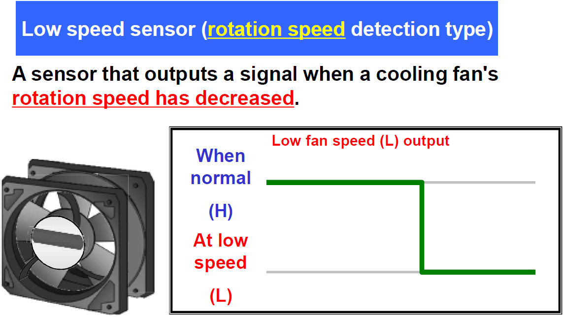
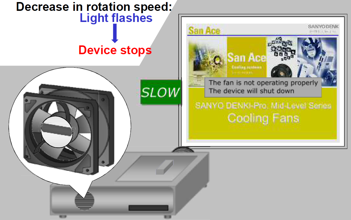
Another type of high and low signal sensor is the low-speed sensor. As its name implies, a low-speed sensor’s signal will switch when the rotation speed of the fan falls below a preset threshold, e.g., from 8000 RPM to 3000 RPM, or from 8000 RPM to locked rotor condition, 0 RPM. An overview is shown in Figure 4, where the fan speed falls below the threshold or trip point. Figure 5 shows an example of a low-speed sensor used in a laser projector application. Laser projectors are prone to accumulating dust and debris over time which impacts a fan’s cooling performance. Sanyo Denki has developed a robust cooling fan for this application that incorporates various types of sensors discussed here.
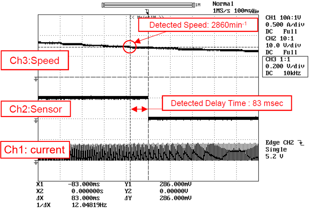
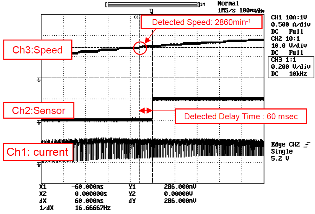
The sensor waveform behavior shown in Figures 6a and 6b depict a customized San Ace fan with low-speed sensor designed to operate at 4100 RPM nominal and set to trigger the sensor output (low or high) if the detected speed in the application is within 2870 RPM +/- 10%. With the implementation of such type of sensor, there is some response time associated which is considered normal in fan designs. The detected delay time specification in this custom fan sensor example is designed to not exceed 2 sec.
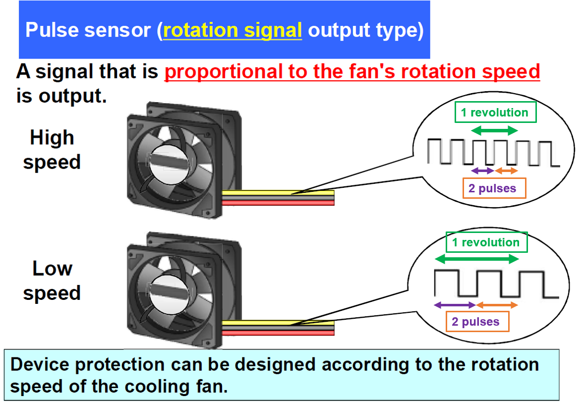
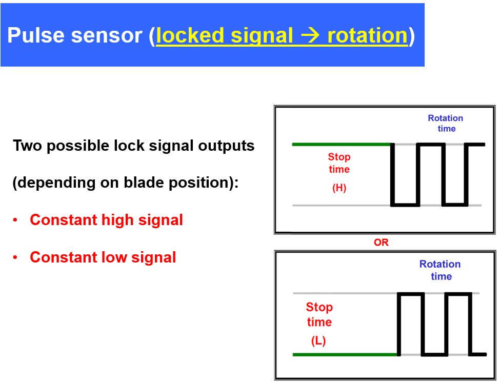
A pulse sensor, otherwise known as tach or tachometer sensor, is a data-rich sensor with an output that gives the user information on the speed of the cooling fan in RPM. The output signal from a pulse sensor has its namesake from the shape of the waveform, as shown in Figure 7. The rapid switching between the high and low signal can be interpreted as RPM for the fan, and the circuitry required to read pulse signal is readily available on the market. Sanyo Denki’s standard pulse sensor output is 2 pulses per 1 revolution. If the fan does experience a locked rotor state, the pulse sensor will output either a constant high signal or constant low signal (Figure 8). Note that sensor specifications are for a single fan. When using multiple pulse sensors, they cannot be aggregated or combined to generate one pulse sensor signal. This also applies to other types of sensors discussed here. Individual fan sensor RPM must be polled separately.
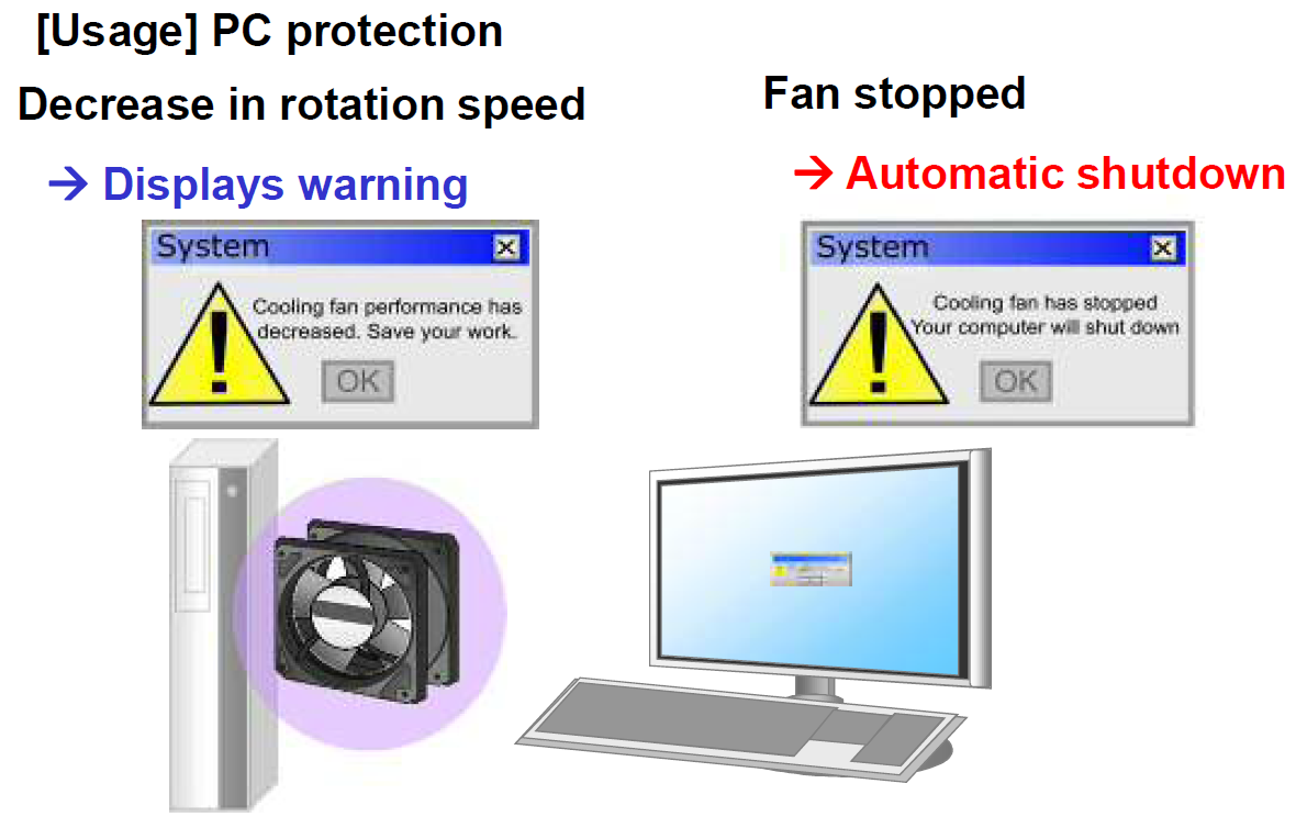
As the pulse sensor provides the user with actual speed of the fan, it is valuable in many aspects. For example, if a company implements incoming quality control (IQC) on Sanyo Denki cooling fans, then fan speed at a known input voltage can be measured and compared to expected values. Another application is to alert the user if fan speed in a system has decreased and even take actions to shut down a system in case the fan has stopped, as represented in Figure 8. In the case of utilizing a 4-wire fan with PWM input function, the pulse sensor provides necessary feedback to ensure that the fan is operating at the correct RPM which corresponds to the PWM input duty, such as in Figure 9’s example application.
Speed sensors are a useful tool for providing feedback on fan performance. The various types of speed sensors – lock, low-speed, pulse, all can be used for specific scenarios to alert the user if the fan is operating normally or if there is a failure such as a locked rotor or low speed. Having this information is crucial for preventative maintenance. The simplicity of a lock sensor or low-speed sensor has advantages for straightforward logic alarm circuits, whereas the data-rich pulse sensor can provide precise information about fan operation and requires a receiver to read and interpret the pulse output into fan RPM.
This article has overviewed the differences between three common speed sensors and shown examples of how each sensor is adopted in a system. Having a system that considers fan sensor feedback can protect against overheating and help extend longevity of the electronic components being cooled, such as ICs, CPUs, GPUs, battery packs, or PSUs. Designing robust, fail-safe cooling systems would therefore contribute to reducing electronic waste and contribute to protecting the global environment.
There are further uses for a pulse sensor, which will be explored in combination with 4-wire Sanyo Denki fans incorporating PWM input functionality. Tying together PWM input technology with pulse sensor feedback is a common method for systems to vary cooling fan speed based upon the thermal requirements of a system in real-time, which helps a system save energy and run more efficiently.
Written by Jerry Wu, Vik Khanikar
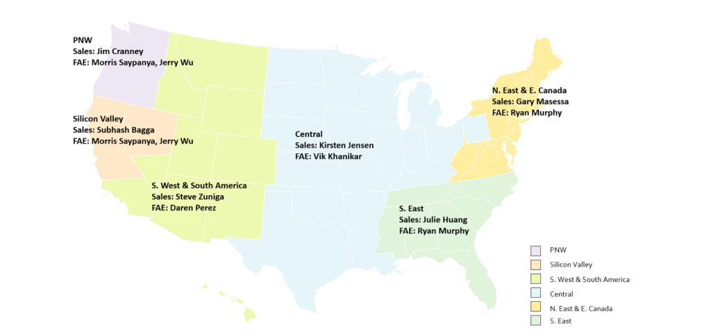
Our experienced application engineers and field engineers will provide support on sensor customization or any other technical support for your equipment.

[…] Easy Guide to Sensor Feedback on Cooling Fan Performance […]
[…] Easy Guide to Sensor Feedback on Cooling Fan Performance […]
[…] wire controls the speed of the fan based on the PWM duty cycle (see the previous article called Easy Guide to Sensor Feedback on Cooling Fan Performance written by Jerry Wu). This circuitry has an internal pull-up resistor as shown in the diagram […]