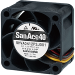
What Is the Safety Protection Feature?
The safety protection features are protective measures incorporated in our DC cooling fans. This article will describe the type and function of each feature.
But First, DC Fan Lead Wire Definition
 DC fans are available in two, three, and four-wire configurations as shown below.
Two-wire – Power and ground, fans run at full speed with no speed control or tach output.
Three-wire – Power, ground, and tach pulse output to monitor RPMs. No speed control.
Four-wire – Power, ground, tach pulse output, and PWM input control for varying speeds.
What Are the Types of the Safety Protection Features?
The main reason to have the safety protection feature is to prevent an overcurrent condition that would cause a temperature rise in the fan coil that can result in reduced performance, permanent damage and/or reduced reliability in the field. The following list highlights various safety features of Sanyo Denki’s San Ace fans.
1) Burnout Protection from Locked Rotor Condition
If the impellor is restricted from rotating, the current to the coil is cut off. The circuit goes into a “safe” mode which attempts to start the fan every 15-30 seconds until the obstruction is removed. This protects the motor from overheating. Once the restriction is removed, the fan will restart automatically.
2) Reverse Polarity Protection
In the event the power (red +) and ground (black -) lead wires are connected in reverse from the power supply to the fan, our two-wire DC fans will not rotate (such as when in the lab or if there is a 3rd party cable/connector house who accidentally miswired the connector). This benefit is from an addition of a Schottky diode into the circuit, which prevents our fans from being damaged. Note however that for three- and four-wire DC fans, they may be damaged due to a reverse current path scenario.
3) Continuous Fan Operation despite the PWM Control Line Being Broken
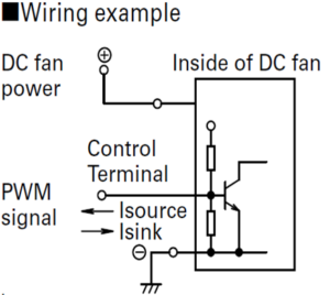
This last one is considered more of a safety protection feature for your system. Let me explain, the PWM lead wire controls the speed of the fan based on the PWM duty cycle (see the previous article called Easy Guide to Sensor Feedback on Cooling Fan Performance written by Jerry Wu). This circuitry has an internal pull-up resistor as shown in the diagram below. In the event this control lead wire is broken (becomes open or disconnected), the fan will run at full speed as if the PWM duty cycle was set to 100%. If there wasn’t this pull-up resistor, the fan would slow down or stop and cause your system to overheat and/or go into Over-Temp Protection (OTP).

While you won’t be able to vary the speed of the fan with the PWM control lead broken, the fan will still provide cooling and prevent your system from overheating as it will run at full speed until you can schedule maintenance to correct the damage.
In closing, while the above safety protection features help reduce issues in the lab and field, it is always recommended to contact your local Sanyo Denki Field Sales Representative and Field Application Engineer to review your design, as we have extensive experience with numerous end applications.
Reference: Technical Material
Written by Gary Masessa
Customization and Technical Support
Our experienced application engineers and field engineers will provide support on sensor customization or any other technical support for your equipment.

[…] Get to know Protection Features in SANYO DENKI DC Fans […]