

Cooling Fan Technology by SANYO DENKI AMERICA
This site is part of SANYO DENKI’s official cooling engineering knowledge base.
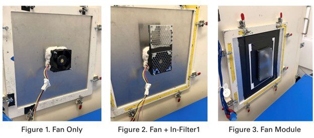
A server customer came to us with a familiar complaint: their hot-swap fan module was loud and power-hungry at the required thermal load. The module uses two SANYO DENKI San Ace 9HVB08 fans. On paper, the fans had plenty of pressure. In the chassis, though, the numbers didn’t add up. We asked them to send the full assembly and ran it through our airflow, acoustic, and power tests.
The intake “in-filter”—an EMI/EMC element located directly upstream of the fan—sat too close to the inlet. Its carrier also used a tight hole pattern with low open-area. Those two details created a double hit: higher entrance losses at the fan face and a large pressure drop across the plate. The result was poor operating airflow, more electrical power draw at the same PWM, and elevated broadband/turbulence noise.
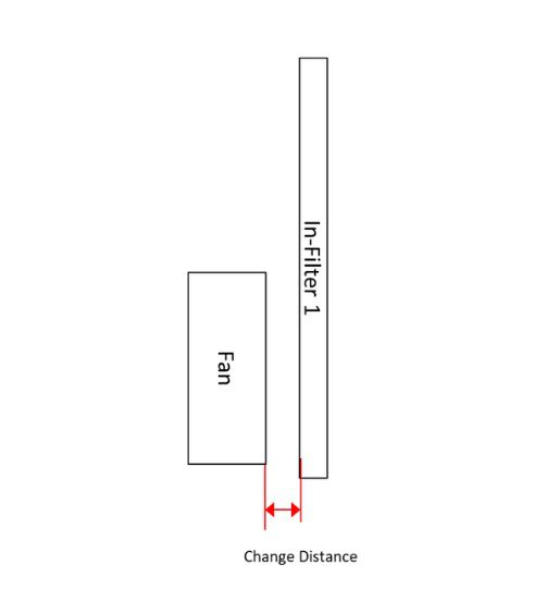
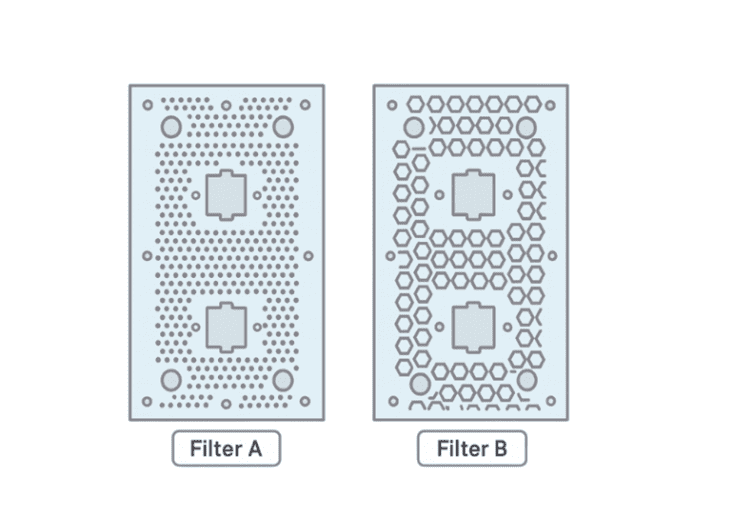
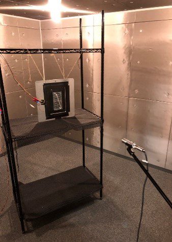
At our Torrance Technical Center, we measured operating airflow (CFM) at the tray’s impedance, electrical power (W) at matched duty, and sound pressure level (dBA) at 1 m. We then varied three things: the in-filter standoff (5 mm → 8 mm), complete removal of the inner intake filter, and a modified EMI filter with a larger hole pattern to increase open-area.
Configuration | Operating Airflow (CFM) | Total Power (W) | SPL* (dBA) |
Original | 226 | 165.5 | 85.8 |
In-Filter1 (5 mm) | 220 | 164.0 | 84.9 |
In-Filter1 (8 mm) | 217 | 161.0 | 83.2 |
Remove In-Filter1 | 227 | 156.8 | 83.0 |
Modified EMI Filter (higher open-area) | 243 | 158.7 | 85.6 |
*Measured 1 m from system center. Values are module-level; system results vary with full chassis impedance. |
Two patterns are clear. First, proximity drives noise: moving the obstruction away from the inlet plane dropped sound by about 2.6 dB(A) at 8 mm. Second, restriction drives watts: eliminating the inner intake layer cut power roughly 5.3% with essentially flat airflow. The open-area change was the big airflow win—about +7.5% CFM and −4.1% power versus baseline. With that extra headroom, you can reduce PWM duty to reclaim the noise margin.
This tray used four filters—two on each side. The in-filter is the inner element on the intake side, placed directly upstream of the fan for EMC. Its location makes it a top contributor to entrance losses: if spacing to the fan plane is too small or the perforation open-area is low, the inlet velocity profile skews, separation increases, and pressure loss spikes. At a given PWM, the fan sees higher system resistance, so electrical power rises and broadband/turbulent noise increases—even if RPM is essentially unchanged. If the system still can’t meet its thermal target, teams often bump PWM to compensate, which then raises RPM and sound further.
We didn’t change the fan. We changed the geometry.
Free-air CFM doesn’t run your server; the operating point does. Anything you place directly in front of a high-pressure fan shapes that point. A few millimeters of spacing and a few percentage points of open-area can be the difference between meeting the thermal spec at modest PWM—or burning watts and noise margin for the same result. In this case, simple changes recovered airflow headroom and reduced energy, with measured noise benefits when the near-inlet obstruction was relieved.
Book an airflow/acoustic review at SANYO DENKI AMERICA’s Technical Center in Torrance, CA. Contact us through the Cooling Solutions inquiry form, or explore the San Ace fan lineup to spec the right fan for your tray.
SANYO DENKI has been a trusted provider of cooling solutions for various industries, with fans being a crucial component in many advanced devices. Contact us for a quote, or to discuss your device's customization requirements.
Our experienced application engineers and field engineers will provide support on the customization or any other technical support for your equipment. Contact our representatives or distributors to start discussing your next project.
Contact Us