


Cooling Fan Technology by SANYO DENKI AMERICA
This site is part of SANYO DENKI’s official cooling engineering knowledge base.
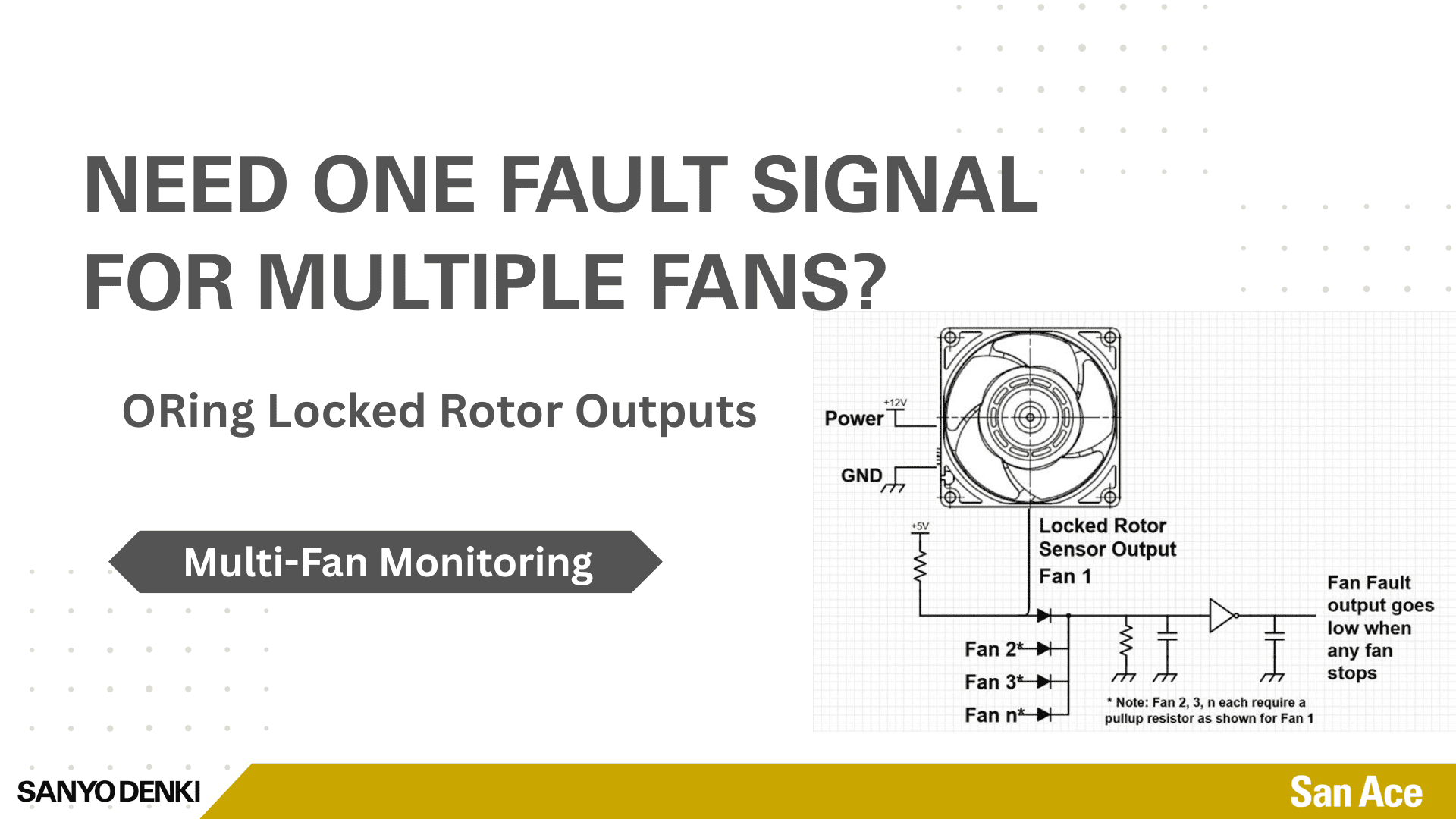
In applications that use multiple fans per system, a simple way to monitor for a fan fault, is to provide a single signal indicating when any fan fault occurs. This brief article explains one method for implementing that approach.
In some designs, customers don’t want to monitor the RPMs of each fan by using the pulse tach output, despite the capability to measure the service life or health of the fans and anticipate replacement timing (Link: An Overlooked Benefit of a Pulse Sensor of a DC Fan). Instead, they want a simpler way to be notified if the fan impeller stops rotating, particularly in systems that have multiple fans. By choosing fans with locked rotor sensor, this requirement can be accomplished.
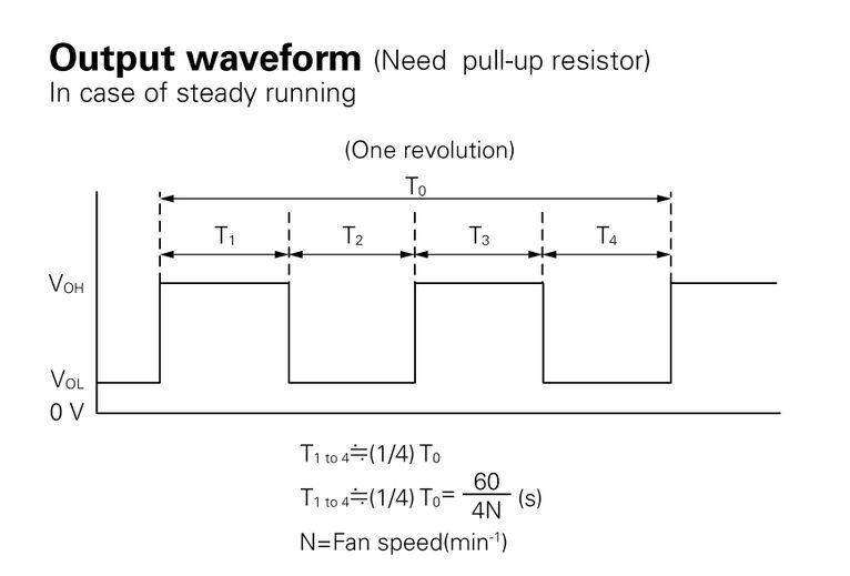
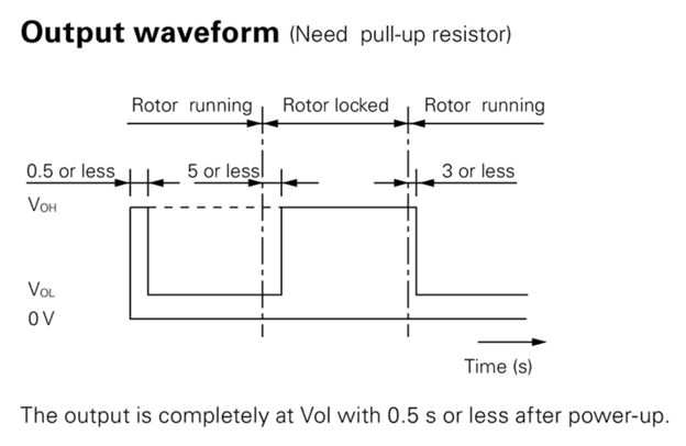
Unlike a DC fan with a pulse tach output (see waveform 1 below) which provides real-time RPM measurements, the locked rotor output only provides an active high logic level when the impeller stops rotating as shown in waveform 2.
As shown in waveform 2, once the fault is corrected (such as removal of an obstruction to the impeller), the locked rotor output returns to an active-low state.
By using an ORing topology built from off-the-shelf diodes, capacitors, resistors, and a logic-level inverter (if desired), an unlimited number of fans can be monitored using a single fault signal. Should one fan fail, the system can be flagged to apply OTP (Over Temp Protection) countermeasures. As you can see in the schematic below, the locked rotor output from each fan feeds a diode that performs the ORing function. If any fan fails, one master fault signal is generated. The inverter is optional depending on logic level for your system.
The primary limitation of this approach is that it does not identify which specific fan caused the fault. However, it does provide immediate notification of a fan failure, allowing the system to take action and prevent overheating.
Please contact your local SANYO DENKI representative or Sales Engineer, if you have any further questions.
Written by Gary Masessa
This article is part of SANYO DENKI AMERICA’s San Ace cooling engineering knowledge base, sharing practical guidance engineers use when working with DC fans in electronic cooling designs.
SANYO DENKI has been a trusted provider of cooling solutions for various industries, with fans being a crucial component in many advanced devices. Contact us for a quote, or to discuss your device's customization requirements.
Our experienced application engineers and field engineers will provide support on the customization or any other technical support for your equipment. Contact our representatives or distributors to start discussing your next project.
Contact Us