A guide to Size The Pull‑Up Resistor for DC Fan Tach Sensor

Picking the Correct Pull-Up Resistor Value for Your DC Fan Tach Output Sensor

What Is a Pulse Tach Output Sensor?

The pulse tach output sensor from our DC fans provides real-time RPM measurements and monitors the health of the fan. It helps determine when the fan’s service life is approaching its end, as well as detecting any abnormalities —making it a valuable tool for scheduling maintenance.

See related article: An Overlooked but Useful Benefit of the Pulse Tach Sensor

Why Do Designers Ask About Measuring the Output

We often receive questions from customers who are starting new designs, particularly around how to measure the pulse tach output. This article explains what to consider when designing a circuitry to properly read this output.

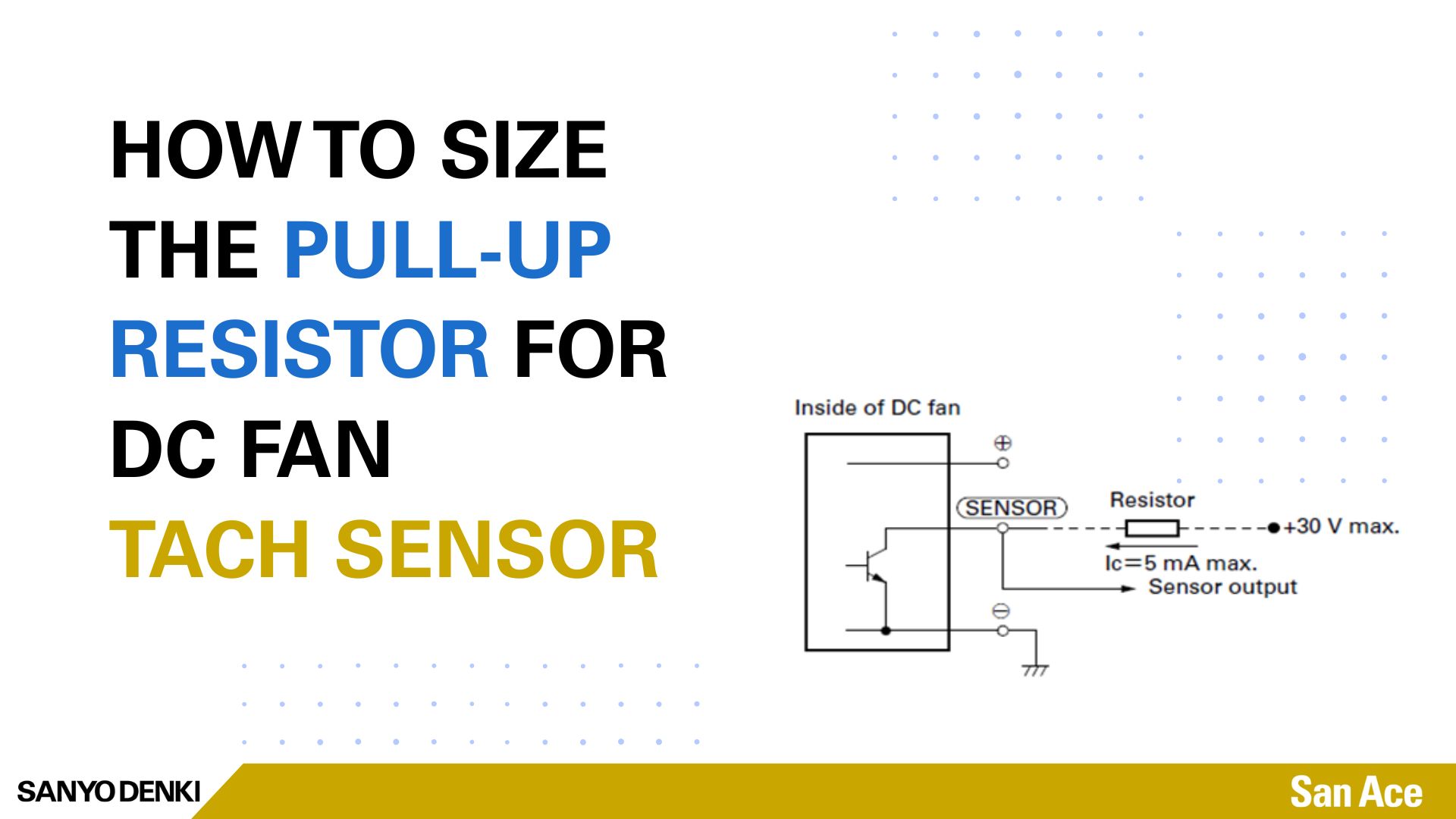
Note that, unlike the PWM Input which has an internal Pull-Up resistor (see article: Get to know Protection Features in a Sanyo Denki DC Fan ) the pulse tach output does not have an internal pull-up resistor. It must be added externally by the customer, please refer to the schematic below for proper setup.

Setup

 output circuit specifications for pull up resistor output circuit schematic for DC fan


Sizing the Pull-Up Resistor: Don’t Exceed the Maximum lc Value

For example: 5mA Max 

When choosing an external pull-up resistor, make sure Ic (collector current) does not exceed 5mA—going above this will damage the fan.

Use the Ohm’s Law formula to determine the appropriate resistor:

R = V / I, or specifically, Rpu = VCE / IC

For example:

  • If you’re using a 12V supply:
    R = 12V / 5mA = 2.4kΩ Min.


Choosing a Common Resistor Value

Common standard values like 3.3kΩ, 3.6kΩ, or 4.7kΩ can also be used. These values (with a VCE  of 12V) result in the following collector currents which are all below the 5mA maximum limit:

  • 3.3kΩ → 3.6mA
  • 3.6kΩ → 3.3mA
  • 4.7kΩ → 2.5mA


What to Expect for the Output Signal

With the correct pull-up resistor in place, you can now measure the pulse tach output. You should see two pulses for every impeller rotation, as shown in the waveform diagram below.

DC Fan pulse tach output waveform with pull up resistor

In Closing

To properly use the pulse tach output sensor:

  • You must add an external pull-up resistor
  • Ensure Ic stays under 5mA

Failing to do this may result in permanent damage to the fan.

Need Help?

Contact your local SANYO DENKI representative or sales engineers if you have further questions.

Written by Gary Masessa

About SANYO DENKI

SANYO DENKI has been a trusted provider of cooling solutions for various industries, with fans being a crucial component in many advanced devices. Contact us for a quote, or to discuss your device's customization requirements.

Our experienced application engineers and field engineers will provide support on the customization or any other technical support for your equipment. Contact our representatives or distributors to start discussing your next project.

Contact Us

Leave a Reply

Your email address will not be published. Required fields are marked *